Mining & Smelting Magazine, June 1862
The appointment of a royal commission to inquire into the condition of the metallic mines of the kingdom has naturally drawn attention to the various appliances by which the labour of climbing ladders may be avoided. It is pretty well agreed that, in the present state of engineering science, some mechanical means ought to be adopted for raising the miners from deep metallic mines; but opinions differ widely as to what those means should be. In Cornwall there is a large party who object to the use of the skip, or any other similar appliance, in the raising of men, principally on the ground of its being dangerous, and who believe that the man-engine is the only machine properly applicable in the varyingly inclined shafts of metallic mines; but there is also an influential party in the county who take a different view, and maintain that with proper care men could be raised with perfect safety in the ordinary skips. As the subject is evidently one of considerable importance, and as an accurate knowledge of the conditions connected with the installation of the man-engine is necessary in order to be in a position to understand the merits of the discussion, we give the following descriptions, most of which are founded on M. Moissenet’s memoir in the Annales des Mines (5th Series, vol. xv, p. 1), with all additional information as to what has been done up to the present time.
While in collieries, from the earliest times, the workmen have been drawn up by the same means as those used for extracting the coal, this does not seem to have been the case in any metallic mining district in the United Kingdom, or on the continent; in Cornwall, in the Hartz, and in the Erzgebirge, the miners still continue to climb up by ladders. The most obvious cause of this difference is, of course, in the fact that while in collieries shafts are generally vertical, in metallic mines they are commonly inclined at various and frequently changing angles. The original notion of the present form of man-engine was conceived in 1883 by Her Dorell, then at Zellerfeld; and the first engine was placed, in the same year, in the Spiegelthai shaft, 110 fathoms deep. The principle on which the engine was constructed was very simple: it consisted of two rods, to which an alternative reciprocal motion was given, furnished with platforms, from winch the miner passed alternately in his ascent or descent. This machine, which received the name of Fahrkungt, and •was described in Karsten's Archiv, vol. x, was found so successful here, that another on a similar principle was put up in 1835 at the Georges Wilhelm mine, on a shaft 225 fathoms deep, underlying2 feet in a fathom: these were followed by numerous others in various German and continental mines. In the cases mentioned, and indeed in almost every other case, the rods were of wood, like pump rods; but in 1836, when it was proposed to put analogous machines on still deeper shafts, like the Sohreiberfeder Schaeht and the Samson shaft of Andreasberg, it was feared that such rods would be too heavy, and it was resolved in consequence to replace them by wire rope. An arrangement of this kind was placed in the Samson shaft, which, in November, 1841, had attained the depth of 420 fathoms, and which it was expected would have to be sunk to the depth of 480 fathoms. This shaft was sunk on the course of the lode, and from surface to 210 fathoms had an underlie of 6 inches in a fathom; from the 210 to the depth of 300 fathoms it was vertical; below the 300 it took again an underlie of 6 inches in the fathom, but in an opposite direction, to the depth of 330 fathoms, below which it went down again vertical. The first movement made to introduce these machines into Cornish mines was made in 1834 by Mr. Charles Fox, who offered considerable pecuniary prizes, first to the engineer who designed the best engine, and next to the mine which should erect it. Mr. Michael Loam gained the prize for the best design; and the adventurers of Tresavean mine were induced to erect one, being subsidized by a considerable subscription. This first engine, which went to work in January, 1842, and only extended at first to the depth of 25 fathoms, consisted of two rods (worked by a water-wheel) moving alternately with a 6-ft. stroke, the platforms on each rod being 12 feet apart. This experiment was so far successful that it was determined, on the advice of Mr. Loam, to apply steam-power, and to extend the machine to the bottom of the mine. For this purpose a 36-in. cylinder engine, with a 6-ft. stroke, was erected, the stroke of the rods being extended to 12 feet, while the platforms remained the same distance apart. Thus modified, the engine was. put to work to the depth of 140 fathoms on the 25th October, 1842, and finished to the depth of 290 fathoms in June, 1843; the mine being at that time 310 fathoms deep. A second engine, on the same principle, was put in at the United mines in 1845 by Messrs. Hocking and Loam; it extended to the depth of 210 fathoms, and is still working. Tresavean mine having been abandoned for some years, of course the original engine put up at that mine no longer exists. The principle of those engines was that of the original Fahrkunst, that is, two rods oscillating reciprocally. In 1851, however, the late Captain Puckey, in connection with Mr. West, engineer, of St. Blazey, conceived and adopted a new .system at Fowey Consols mine. This consisted in the substitution of a single rod for the double rods, this rod being furnished with platforms 12 feet apart, while a series of sollars, a similar distance apart, were placed in the shaft, on each side of the rod, in such a position as to correspond with the levels of the platforms at the end of each stroke. In this modification of the engine the miner, on leaving the platforms at the end of the up or down stroke, waits on the sollar until the next up or down platform comes to him. This type of man-engine, as we shall point out farther on, is a decided improvement on the old double-rod type, and engines on this plan have since been put up at Levant, Dolcoath, Cook’s Kitchen, Carn Brea, Par Consols, and Wheal Reeth. Consequently there are at present eight man-engines working in the county—one double-rod at the United mines, and seven single rods at the mines named. Tabulating the leading particulars of these engines, we have the following statement, which shows the depth to which each engine extends, the particulars of the motive power working it, the relative number of strokes made by the motive-engine for one of the man-engine rods, the rate at which the rods themselves are made to move, the duration of the journey, and the velocity of the miner. In every case the length of the stroke of the man-engine rods is the same – 12 feet.
|
Mines |
Depth of Engine Shaft |
Particulars of Motive-Engine |
Relative no. of Strokes |
Rate of Man-Engine |
|||||
|
Size of piston |
Length of stroke |
No of strokes |
No. of strokes |
Journey |
Velocity |
||||
|
|
Fathoms |
inches |
ft |
in |
Per min |
|
Per min |
min |
Per min |
|
1. United Mines (double rods) |
210 |
32 |
6 |
0 |
18 |
6 |
3 |
17½ |
72 |
|
2. Levant (Single rod) |
200 |
20 |
3 |
8 |
40 |
10 |
4 |
25 |
48 |
|
3. Dolcoath |
220 |
20¼ |
5 |
0 |
42 |
12 |
3½ |
30 |
42 |
|
4. Carn Brea |
132 |
26 |
6 |
0 |
16 |
4 |
4 |
16 |
48 |
|
5. Par Consols |
220 |
24 |
6 |
0 |
25-30 |
5 |
5-6 |
20 |
68 |
|
6. Wheal Reeth |
188 |
30 |
9 |
0 |
5-6 |
1 |
5-6 |
16½ |
68 |
|
7. Fowey Consols |
280 |
Water wheel, 30ft by 6ft. |
5-6 |
25 |
68 |
||||
|
8. Cook’s Kitchen |
190 |
Water wheel, 52ft by 3ft. |
3½ |
27 |
42 |
||||
At the United mines and Fowey Consols the shafts are perpendicular the whole way. At Levant, after underlying slightly east, the shaft changes to a considerable west underlie in depth. At Dolcoath, the first 50 fathoms are perpendicular, but afterwards the underlie is south, 18 inches to 2 feet per fathom. At Carn Brea the shaft is nearly perpendicular to the 80, below which it underlies 1 foot in a fathom south. At Cook’s Kitchen the shaft is perpendicular to the 60, and below that underlies 2 feet per fathom south.
Excluding the cases stated of Fowey Consols and Cook's Kitchen, the motive-engines are the ordinary Cornish rotary steam-whims double-acting, with vertical cylinder and beam; except in the instance of Wheal Reeth, where an ordinary pumping engine is used, and the rod is attached directly to the beam. Where a rotary engine is used, the rod is attached to the steam-engine by means of an ordinary balance bob, in the same manner as pump rods would be attached, a line of flat rods of greater or less length being used for forming the connection between them. In the cases of the United mines, Fowey Consols, Cam Brea, Cook’s Kitchen, and Par Consols, the flat rods receive their motion from crown-wheels working in 8 vertical plane; in Levant and Dolcoath, from wheels working in a1 horizontal plane. This difference of arrangement has arisen from the nature of the motive engines to winch the man-engine rods had to be connected. That at the United mines was used to work a crusher, and consequently the wheels were most conveniently placed vertically. Those at Levant and Dolcoath, on the contrary, having been employed to work the old-fashioned vertical-axe whim, it was necessary to accommodate the movement to them, and consequently Mr. Hocking was driven to adopt the horizontal crown wheels. The vertical ones are, however, much preferable, and being adapted to the modern form of drawing machine now in use, may be considered as the type to be adopted in future. The mode of connection is very simple: it consists of a crown and pinion-wheel, the latter (say 2 feet in diameter) attached to the axle of the motive power, and the former (say 14 feet), in which this works, to the periphery of which the rod connected with the bob is attached. The dimensions given are those of the cogwheels at the United mines, but, of course, the relative sizes of these will vary according to the relative number of strokes required to be made by the motive-engine to each stroke of the man-engine rods. These wheels are thrown in and out of gear in the ordinary manner, by which the man-engine is connected or disconnected from the motive-engine. In the case of the water-wheel at Fowey Consols, it was considered that its mass alone was insufficient to secure the proper regularity of the motion, and consequently a fly-wheel, weighing fourteen tons, has been added, worked by cogs at three times the rate of the water wheel.
When the man-engine receives its motion from a vertical wheel, there is no difficulty in making the connection between it and the bob of the man-engine rods, inasmuch as they both work in the same plane. But when the motion is given by a horizontal wheel, as at Dolcoath and Levant, the connection is attended with some little difficulty, in order to bring within as narrow limits as possible the line of lateral variation of the connecting rods. At Dolcoath this is effected in the following manner:- The total distance between the horizontal crown-wheel and the shaft is about 27 fathoms. Between this there is first, an 8-inch rod, 24 feet long, attached at one end to the wheel, and at the other to another rod, at right angles, 22 feet long, working like a fend-off bob. To the point of junction of these two rods is connected the line of rods (7½ inches square) attached to the bob of the man-engine. The effect of this arrangement is, that the lateral variation, which at the head of the first piece of rod is 12 feet (the diameter of the wheel), is reduced by the action of the other rod at right angles to a variation of only one foot, which is not material.
The rods of the man-engines, like those of pumps, are of Norway pine, of the best quality, with an average length of about 36 feet. The size in the rods of the various engines varies as follows:—
Fowey Consols, Levant and Cam Brea.. 8 inches through their entire length.
Cook's Kitchen and Far Consols.. .. Succession of 8 inches and 7 inches.
Dolcoath .. .. .. .. .. Succession of 8 inches, 7 inches, and
6½ inches:
United mines .. .. . 7½ inches first 60 fathoms.
„ .. .. .. 7 inches the 100 following fathoms.
„ .. .. .. .. 6½ inches the last 50 fathoms.
They are joined together like the pump rods, that is, by four wrought-iron strapping plates, generally about 1 inch thick, 5 inches wide, and from 10 to 12 feet long; these are screwed two and two together with 1¼ inch bolts 18 inches apart, so that each rod is held by eight bolts.
The platforms are of good deal, or oak,
which is better, 14 inch thick, but of varying size. In the double-rod
engine of the United
mines the platforms are 18 inches wide by 15 inches deep, with a space of 6
inches between them. In the single-rod engines at
Dolcoath and Fowey they are respectively 16 inches and 12 inches square.
This seemingly unimportant mutter .being really one involving to some extent
the question of safety, I .shall dwell upon it for a moment.
The only danger connected with the man-engine arises from the possibility of slipping the foot, or from carelessness in exposing the head or shoulders beyond the, proper limits, and thus subjecting them to collision with the platforms, sollars, or walls of the shaft. Now there is less danger of slipping in stepping on a 12-inch platform than on a larger one; and besides, the more restricted the space, provided it is sufficient for the two feet, the more the miner will be obliged to hold himself upright on the platform, and thus avoid the risk of exposing his head or shoulders to collision with the sollars. (in the case of the single-rod engine). The proper space between the two sollars generally would be from 22 to 24 inches. Now with a 12-inch platform there would be on each side a free space of from 5 to 6 inches, while with a 16-innh platform this is reduced to 3 or 4 inches, and consequently the possibility of collision, in case of carelessness, proportionately increased, consequently a 12-inch platform seems the safest size.
These platforms (which it need scarcely be said should always be horizontal, whatever the underlie of the rod) are fixed in the rod by iron brackets. At Dolcoath this is done by bar-iron, 2 inches by 4 inch, and at Fowey Consols by angle iron. In every engine, a handle of ¾ inch round iron commences 4 feet above each platform, and extends up 2 feet long.
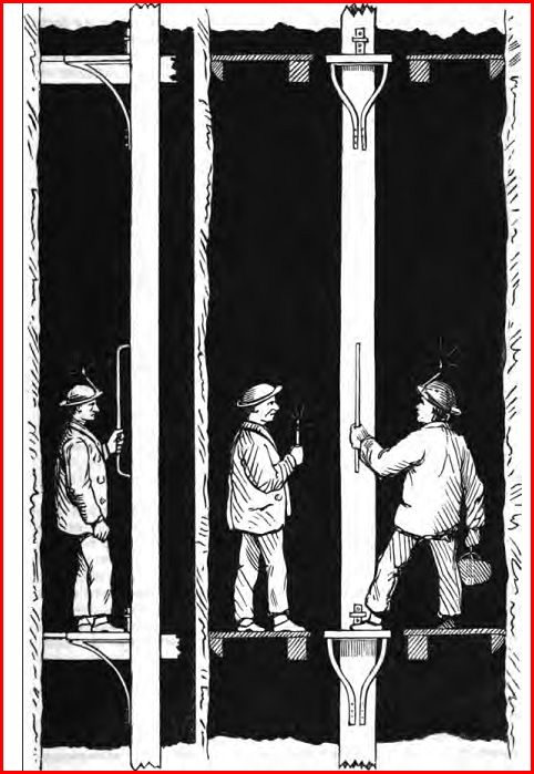
The drawing (fig. 1), giving a front and side elevation of the single-rod type of man-engine, snows its general arrangement, and the manner in which the men step in and out at the end of each stroke. Besides these more general particulars, there are a few special details of such practical importance as to make it advisable to give a few particulars concerning them. These are, the guides, sheaves, angle or V bobs for breaking the underlie, catch-pieces, and balance bobs. All these follow, more or less closely, the similar arrangements employed in pit-work.
Fig 1 Cornish Man-Engine
|
|
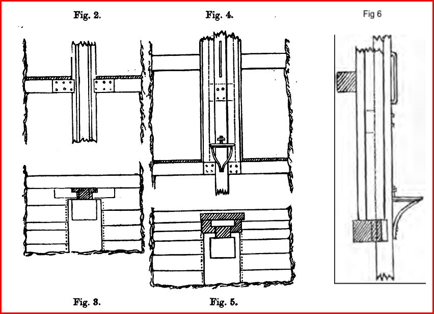
Guides. The drawings in figs. 2, 3, 4, 5, and 6,-show the two arrangements of guides employed at Fowey Consols. One consists of a short bar fixed transversely at the back of the rod, the ends of which work in two longitudinal guides forming a groove; this arrangement is shown in figs 4, 5, and 6, of which fig. 4 is a front elevation, fig. 5 a ground plan, and fig. 6 a side elevation. The other arrangement, on the contrary, has a short groove in which two long pieces work, which are attached laterally to each side of the rod; figs. 2 and 3 will make this plain* In all cases the rods are protected by linings of beech or elm, and the guides are firmly secured by pieces of substantial timber fixed in the shaft. At Dolcoath for the perpendicular, or only slightly inclined portions, a strong plate is fastened at the back of the rod; this works on a fixed horizontal beam, in which two cramp-irons are placed, which extend over the projecting edges of the plate, and thus form grooves.
Sheaves. The sheaves are of cast iron and are always placed behind the rod in the shafts, firmly secured to pieces fixed in the shaft. Their diameter should not, if possible, be less than 2 feet; at Dolcoath, according to the space disposable, they range from 2 feet 6 inches to 18 inches; the rims should not be less than 3 inches deep. The rod is secured against any vibrations which might cause it to get out of the sheaves by the guides or catch-pieces. A plank of beech, 18 inches thick, used as a lining to preserve the rod from the effects of friction, is fixed by staples on that face of the
|
|
Angle-bobs:- The most simple angle-bob for breaking the incline is that called the V bob, which is an isosceles triangle, the angle at whose summit is the supplement of the obtuse angle comprised between the two inclinations. These bobs, being those usually used for breaking the angle of pump rods, are sufficiently well understood; it is evident that the points of each of the arms of the V bob describes an arc of a circle whose radius is equal to the length of the-side of the V bob, and that upon the length of this radius depends-the amount of the deviation. As in the case of man-engine rods, the chord of the arc (the length of the stroke) is always 12 feet, with a 24-ft. bob the deviation will be 9216 inches.
|
|
Travelling-bob, between the axles, a platform is
fixed, the two neighbouring platforms, above and below, being on the main rod.In certain parts of Dolcoath shaft, where the
inclination augments gradually without any sudden angle, the rod coming too
close to the hanging wall of the lode, it suffices to keep it sufficiently off,
to attach the next piece of rod not to the end of the last piece but behind it,
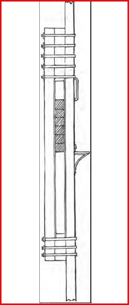
putting a short piece between, and strapping and bolting the whole together. Catch pieces:- The accompanying sketch (fig.
7) shows the catch-pieces in use at Fowey Consols, which it will be seen do not
differ materially from those used in pump rods, the object being to prevent, in
case of breakage, a greater fall than 12 feet, the length of the stroke. These
catch-pieces are placed at intervals of 40 fathoms apart, and in the Fowey
Consols shaft are composed of six pieces,
each 8 inches square, forming a support 4 feet deep. Behind the catch-pieces
another longitudinal retaining piece, 18 feet long, and also 8 inches square, is
securely strapped and bolted by iron strapping-plates 2 inches by 1 inch at the
top and bottom to the main rod, leaving an intervening space of 12 feet long by
11 inches wide, which is kept by the short intervening pieces, the upper one of
which is 4 feet long, and the lower only 2 feet. Both the main rod and the
retaining-piece are preserved from friction by the usual lining. It will be seen
that these catches work very efficiently as guides. Balancw-bobs:- The rods should be as nearly
as possible balanced, so that when they are empty the power required to move
them shall be little more than the friction. With the exception of the case of
the United mines, presently referred to, the ordinary pit-work balance-bobs are
universally used. The amount of balance used at Dolcoath is 30 tons, distributed
as follows:-
|
|
Tons |
|
At surface.—Balance behind crown-wheel |
5 |
|
Large bob at mouth of shaft |
8 |
|
Balance at 90 fathoms |
7 |
|
Balance at 120 fathoms |
10 |
|
|
30 |
At Carn Brea there is a very large bob at the surface, with a balance of 25 tons, and another at the 70 with 7 or 8 tons. At Cook's Kitchen the balance of 20 tons is distributed as follows: at surface, 7 tons; at 42 fathoms, 7 tons; and at 111 fathoms, 6 tons. At Levant there are four bobs with a balance of about 33 tons. At Fowey Consols there are three, one at surface, and two in the shaft. The balance-bobs are usually attached to the main rod by a long connecting-rod, at least 60 feet in length; this length, with the elasticity of the connecting-rod, allows it to be connected with the main rod in the same manner as the retaining-piece in the catches. At Fowey Consols the connecting-rods are of 3-inch round iron.These balance-bobs work very well, but are costly, not only in themselves, but in consequence of the considerable room they occupy, requiring frequently the cutting of heavy plats where the old workings are not sufficiently large, or not conveniently placed. The latter difficulty may be sometimes met, as in the case of Dolcoath, where, at the depth of 120 fathoms, the lode had been worked for a great width, but with a considerable underlie, so that to put in a bob in these workings it was requisite that it should be inclined like the underlie of the lode and the rod, so as to work in the same plane as the latter. This arrangement is also sometimes adopted with pump rods. The usual system, however, is to put in the bobs behind the rod in a direction at right angles to the length of the shaft. The same well-known principles which apply to distributing the balance in the case of pump-rods also applies to the balancing of man-engine rods; hence it is evidently more advisable to distribute the balance throughout the depth of the rod than to accumulate it in any one place. The main point to aim at is to insure that the rods shall always work by extension and not by compression. Hydraulic balances would also be evidently well suited for man-engine rods, wherever they can be conveniently used, particularly as they avoid the oscillation which, under the best arrangements, is to a certain extent inseparable from the use of the ordinary bob. At the United mines there are two ordinary balance-bobs at the mouth of the shaft, and three balance levers in depth ; one at the adit, one at 40 fathoms, and the third 72 fathoms deeper. A sketch of these levers is given in Plate IV of the Report of the Polytechnic Society for 1845. Although the levers are economical in their first cost, there is a considerable friction from the use of cogwheels, so that they have not been found to answer well on the whole, and have not been adopted in any subsequent engine. Signals:- The man-engine compartment is always provided with a "knocker-line," for signalling to the surface. At Fowey Consols IJ-inch galvanized wire-rope is used.Weight of Man-Engines:- The density of Norway pine being .58, a rod 8 inches square and 100 fathoms long will weigh about 4 tons 6cwt. In the same length there will be about twenty junctions of the rod, the iron used about which, for strapping-plates, &c., each weighing about 6 cwt., gives a total weight of 6 tons for strapping iron per 100 fathoms. The iron required for the fifty brackets for the platforms in the same length will weigh about 7¼ cwt; and that for the corresponding handles about 3½. The total weight of a rod 100 fathoms in length will, consequently, be about as follows:-
|
|
Tons |
Cwts |
|
Wood in the rod |
4 |
6 |
|
Strapping-plates, &c., for junctions |
6 |
0 |
|
Brackets and handles |
0 |
11 |
|
Sundry pieces: guides, catches, strapping-irons, bolts, &c |
1 |
18 |
|
Total |
12 |
10 |
or 26 cwt. per running fathom. If to this we add the travelling or V bobs, and the connecting-rods of the balance-bobs, we have for the depth of Dolcoath, 220 fathoms, a weight of about 300 tons to be balanced as near as may be by the arrangements stated. Cost of Man-Engines:- The cost of a man-engine is a matter difficult to estimate with any practical accuracy, for the principal outlay often arises from the cost necessary to put the shaft in a state to receive the engine. Assuming, however, that the shaft is in the required state, we may roughly estimate the cost of the single-rod engine at from £2 to £2 10s per fathom, including in this the balance-bobs taken at an average cost. The mere cost of the rods, platforms, &c. (including strapping-plates and the necessary connections), would probably not exceed 25s per fathom, but the balance-bobs run away with money. One of the most recent engines put up in Cornwall, that at Cam Brea, cost, with the steam-engine (26-inch), about £2,300; but then, as we shall show further on, the cost of the motive power should not be included specially in the cost of the man-engine, for under any system of raising men mechanically this power, indeed, a greater power, would be required. The steam-engine is not necessarily employed exclusively in working the man-engine: when the latter is not working, the former may be used or drawing, stamping, or and other required duly; the engine at Carn Brea is used for drawing. The estimate of cost per fathom we have given above is not intended to be taken as accurate; it is merely given to convey a general notion, for we intend.
ECONOMIC CONSIDERATIONS.
Having given the above condensed descriptive notice, we shall conclude by talking a brief review of the following questions connected with this engine. The conditions of working, and the results obtained, and obtainable. The types and power of motive-engines most applicable. Considerations of consumption, expense, and general advantages of man-engines, and particularly of the single-rod type. And a review of the comparative advantages of the man-engine, and other apparatus for raising miners. Condition of working and results. In most metallic mining districts the day of twenty-four hours is divided into three cores (or corps) of eight hours each, thus distributed: from 6 a.m. to 2 p.m., from 2 p.m. to 10 p.m., and from 10 p.m. to 6 a.m., the last core being often wanting. Where a shaft is sinking there are frequently four cores of six hours each, the sump men changing at 8 and at 2.To meet these various, requirements the engine at Dolcoath is worked thirteen hours out of-twenty-four, as follows: from 6 to 9 a.m., from 2 to 8 p.m., and from 10 p.m. to 2 a.m. At Levant they work seven hours out of the twenty-four: from 6 to 7a.m., from 2 to 6 p.m., and from 8 to 10 p.m. It follows from this, that man-engines are far from being completely utilised, that is, the rods are never constantly full. In order to arrive at the maximum power of these machines, it will be necessary, for a moment to imagine a working by which they shall be fully employed. As in both systems, the ascending and descending currents go on simultaneously, it will be only necessary to consider one of them. In the single-rod type every platform may be manned in each up or down stroke, and in the return stroke they can also be manned by those moving in the opposite direction; no platform, in any stroke, need ever be empty. In the double-rod type, on the contrary, the miner only returns to the same rod at every other platform, leaving the intermediate ones as a distinct route for the opposite current; so that, on any one rod, only half the platforms can, under any circumstances, be occupied at the same time. Now, if L be the length of the man-engine in fathoms, and the platforms be always two fathoms apart, L÷2 = P will be the number of platforms on each rod. Let s be the number of strokes per minute made by each rod in the double-rod system, and s the number of strokes per minute made by the single rod. Let n be the number of miners to descend; and let t and t1 be the corresponding times, in minutes, required to send them down by the double and single-rod systems respectively. In the double-rod system, the leading miner of the descending current will arrive at the bottom of the shaft after having occupied successively P ÷ 2 platforms on one of the rods, which will require in time ½ P ÷ s minutes. After the arrival of this leading man of the current, each stroke of the same rod will bring another, so that n miners will be brought down in — minutes; so that we have:- t=½ P + n ÷ s……………(a) With the single rod type of engine, where the miner must occupy successively all the platforms of the rod, we have similarly:-
t’=½ P +n ÷ s’……………(a)
Applying these formulae to a given case, so as to compare the efficiency of the two types of engines, let us take that of a man-engine extending to 220 fathoms deep, having to send down a core of 200 men: here L = 220, P = 110, and n = 200.
In the double-rod type, working at the rate of the United Mines engine, three strokes per minute, where, consequently, s = 3, we have, by formula (a) t’= 55 + 200 ÷ 3= 85 minutes, the time required to send down the 200 men by this form of engine, In the single-rod type, working at the rate of Carn Brea engine, four strokes per minute, and where, consequently, s’ = 4, we have, by formula (b) t ’= 100 + 200 ÷ 4 = 77½ minutes, the time required to send down the 200 men by this type of engine. A result which shows a balance of 7½ minutes in favour of the single-rod arrangement, only working one-quarter quicker. Indeed, a simple consideration of the subject ought to show the great superiority of the single-rod arrangement. For even if the two types of engine worked at the same rate, although the double rod would send down any one man in half the time required by the single rod, the time occupied in sending down any given number of men would be the same m both cases when the current had been once established. But the double-rod engine cannot be worked at the same rate as the single one; for experience shows, that the number of strokes per minute of the former cannot safely exceed half the number of strokes which may be given to the latter: that is, if the one goes 3 strokes per minute, the other may be worked to 6. Accepting, therefore, that while s = 8, s’ may equal 6, we see that the single rod will send down any single man as quick as the double rods, and any given number of men in half the time, the current once established. (It is rather remarkable that there seems to be a wide-spread misunderstanding in Cornwall as to the respective capabilities of the two types of man-engines. While the single-rod type has of late been exclusively adopted, there seems yet to be a notion that the double rods are able to do twice the quantity of work, and are only not adopted because such an amount of work is not required.) To get a general formula for ascertaining the number of strokes per minute, s’ required to be given by a single-rod engine in order to perform the same amount of work as two rods each making s strokes, where, consequently, t = t’, we have from formula (a) and (b):- ½ P + n ÷ s’ = P + n ÷ s’ or s’ = 2s P + n ÷ P + 2n ………..(c)
From this equation it follows:-
1. That s’ is always less than 2 s.
2. And smaller, in greater proportion for the same depth, as the number is greater;
3. That for any given number s’ will increase with the depth. To make these conclusions more intelligible, let us take the case already given where 200 men were lowered to a depth of 220 fathoms in 85 minutes by a double-rod engine working 3 strokes per minute; and let us ascertain by equation (c) the number of strokes per minute of a single-rod engine would be required .to do the same work. Here s’ = 2 x 3 - 110 + 200 ÷ 110 + 2 x 200 = 3.64, that is to say, a little more than 3½ strokes per minute of the single rod would suffice to do the work in the same time as performed by the two rods working each at the rate of 3 strokes per minute. Assuming that s’ = 2 s; and taking the case of a deep mine (say 290 fathoms) sending down 500 men per day, 200 in each of the day cores, and 100 in the night core, we shall find that while the total time required for sending down the 3 cores with the double-rod engine (working 3 strokes per minute) is 4 hours 32½ minutes, the time required to do the same work with the single-rod engine (working 6 strokes per minute) will only be 2 hours 52½ minutes, showing a saving of 1 hour 40 minutes, or more than one-third of the whole time. Where the motive-engine is employed for other purposes, such as drawing stuff, this saving may be of much importance. Motive-engines:- In calculating the useful power required to work a man-engine, it is necessary to consider that besides the useful work performed, there is a dead weight to be overcome in the friction and the slight unbalanced weight of the rods. This dead weight of course varies considerably with local circumstances, and particularly with the underlie of the shaft; at the United mines it was estimated that one-third of the motive power was absorbed in the friction resistances. The weight of a miner may be taken at 150Ibs., and as it is necessary in calculating the power required to assume the maximum that the machine could hold, we shall have, taking account only of the ascending current. In the double-rod system, on one of the rods (take account only of the ascending current) P ÷ 2 platforms are occupied. During one minute these will receive 2 x s strokes of 12 feet, the useful power (x) of which, expressed in pounds raised one foot high, will be:-
x = P X 2.s X 12 X150; or x = P s. 12.150 .... (d.)
In the single-rod system, where the whole number of P platforms are occupied during the stroke of 12 feet, we have similarly:-
x’ = P . s’. 12.150 ....... (e.)
Thus expressed, x and x’ have the same form, which we can readily understand, for the P ÷ 2 miners of the two rods are constantly in movement, while the P miners of the single rod are half their time on the fixed sollars. If we apply these formulae to the cases of the United mines and Dolcoath, dividing the results by 33,000 to get the horse-power required, we have:- United mines x =105.3. 12.150 = 567,000 = 17 1/8 horse-power.
Dolcoath x’ = 110. 5½. 12. 150 = 693,000 = 21 horse-power.
From this hypothesis, which assumes only one ascending current, let us turn to the opposite one, and consider the two contrary currents in motion ; we here find that in the double-rod type there is a permanent equilibrium, the same number of miners always occupying the two rods, but inversely changing from one to the other. In the single-rod engine, on the contrary, the equilibrium is alternative, so to say; that is, if the machine is provided with a sufficiently powerful fly-wheel to store up the motive power derived from the weight of the descending miners, this power will be given out again in the following ascending stroke. The excess of the weight of the rod unbalanced produces the same effect, so that in the two stems there is nothing to overcome but the friction. These observations clearly show the advantages of the single-rod type of engine. If we suppose the shaft vertical , and s = 2s, we shall find that the friction in the guides, &c., without being entirely independent of this relation, is far from being proportional to it. The single rod, with its double weight, and with a movement equal to that of the two rods, will not have double the friction, while during its work it will bring up and send down twice the number of men. Practically, man-engines usually work between these extreme limits; all the platforms are not manned, and the contrary currents are not always equal. However this may be, by the adoption of the single-rod machine, we can profit by the motive -power given out by the weight of the descending core by using a rotary engine with a powerful fly-wheel. As to the type of motive-engine most applicable to the man-engine, it would appear at first sight that, as a reciprocal motion is required, the ordinary form of pumping engine would be easiest applicable. However, sound practical considerations have proved that for both systems, the double and the single, rotary engines are the most suitable. The objection which a priori would suggest itself to the rotary engine is that at the end of the stroke corresponding to the dead point there is, properly speaking, only a slackening of speed, not an absolute stoppage. No practical inconvenience, however, results from this in consequence of a certain play of "the rods due to their elasticity and mass, and to the great slowness of the movement near the dead point. It is generally held that, with a stroke of 2 fathoms we cannot safely exceed a rate of 3 strokes per minute in the case of the double-rod type of engine, and 6 strokes per minute in the case of the single-rod type. These rates are evidently equivalent as to the time left to the miner, when we consider that in the one case both platforms are movable, while in the other case one is movable and the other fixed. A simple trigonometrical calculation of the arcs traversed by the crank at the various periods of the stroke, and of the time occupied, will give us the space traversed by the rod within such periods, and establish this point. M. Moissenet, in his memoir in the Annales des Mines already referred to, has also shown that, by an arrangement which he suggests, the single-rod type of engine could safely be worked as fast as even 8 strokes per minute. In this arrangement the comparative rate of the movement of the rod is expedited in the middle of the stroke, but retarded towards the beginning and end; so that, although the total time occupied by each stroke is reduced from 10 seconds to 7½ seconds, the rate at the beginning and ending of the stroke is not increased. With regard to safety, there can be no doubt that direct-acting engines, leaving an absolute interval of repose at the end of each stroke, would generally be less safe than the rotary engines now used, which only give a very slow movement about the dead point. The man-engine rod, like pump rods, would then have to start suddenly into motion on the admission of the steam into the cylinder, which would evidently give rise to much more danger than the present mode of slow acceleration at the commencement of the stroke. Another important economical consideration also leads us to decide in favour of the rotary engine. As the man-engine is not required to work continuously, but yet at such frequent intervals that the steam must be always kept up and the engineers on the spot, it is important that the engine employed be of such a type that it may readily be applied to other purposes. Now the rotary engine is the only one so applicable, as the direct acting engine can never be used for any other work than pumping, and indeed, as will be shown further on, it would not even be good for much for this purpose if it were modified so as to be safe for the man-engine. Besides, a steam-engine of the power required to work a man-engine in a deep mine, about 35 horse-power, is just the engine required for drawing from a similar mine. Such a sized engine would be useless for pumping in a deep mine, and, in addition, in an immense majority of cases the pumping is required to be continuous and not intermittent. In one case in Cornwall a direct-acting engine has been adapted to work the Wheal Reeth man-engine, by Mr. George Eustice, jun., of Hayle. In this case the arrangement was adopted in order to utilise an old 30-inch pumping engine which happened to be on the mine, and not deliberately adopted as the most advisable course in case entirely new machinery were being erected. As similar conditions may occur in other mines, in whose special case it may be advisable to adopt a single engine working the rod directly, it may be well to state the modifications which Mr. Eustice has used in r order safely to apply this form of engine to working a man-engine. In the first place no expansion of steam is allowed, for this would necessarily be productive of great danger from the sudden shock given to the rod at the commencement of the stroke; the valves are open throughout the whole length of the stroke of the piston. The amount of steam admitted into, and consequently its pressure in, the cylinder is regulated by the engine-man according to the number of men on the rods; if too much steam is admitted the engine will come “in-doors” too fast, and if too little it will come in too slow. In the case of the rod being heavily laden by men going down, it is also requisite to take precautions against its going “out-of-doors” too fast, which would necessarily occur if, at the end of the in-door stroke, the equilibrium valve were suddenly opened with a rod heavily manned. For this purpose a throttle-valve is placed in the top of the vertical pipe connecting the equilibrium valve; by this the rate at which the steam is allowed to pass from the top to the bottom of the cylinder is regulated at will, and with it the rate at which the piston ascends. The whole of this arrangement is very creditable to Mr. Eustice, for circumstances may occur where the adoption of an engine of this kind would be economical, and before he took it in hand it was deemed impossible safely to apply a single-acting engine for the purpose. Consumption and Expenses of Man-Engines:- It must be evident that the consumption of coals, grease, &c., and the other steam-engine charges, must vary with the varying circumstances; and besides, as the motive-engines are usually employed in doing other work, it is not always easy to apportion the respective proportion of cost which should be set down to each. At the United mines the cost on the man-engine has been estimated at £30 per month. In the case of Levant, where the motive-engine also draws from a depth of 79 fathoms, and where its total cost is £25. 5s per month, M. Moissenet calculates that 3/8ths of this should be apportioned to the man-engine, which would give £15. 8s per month. If to this we add 17s for grease, &c., used underground, we have a total monthly cost of £16. In the case of Dolcoath, similarly, where M. Moissenet apportions half the steam-engine cost to the man-engine, he gets a monthly charge of £16. 8s, which, however, is probably much under the mark. As we shall take the opportunity of giving on an early occasion detailed particulars of the monthly cost incurred in working the various man-engines in the county, together with the number of men transported, and the depths, it is unnecessary to dwell further upon these generalities. Advantages of Maw-Engines, particularly the Single-Rod Type:- The enormous loss of labour and time incurred in climbing ladders is well known, indeed, too evident to make it necessary to dwell upon it. To go down by ladders to the depth of 250 fathoms a miner will occupy about 40 minutes, and to climb the same distance he will take about 1 hour, or 1 hour 40 minutes in the descent and ascent. In the man-engine he can go up and down in 25 minutes each way, 50 minutes in all, which gives a saving of 50 minutes, or more than 1/16th, in time of the miner’s working day. The saving in fatigue and labour probably amounts to as much more, so that the saving by the application of mechanical means varies from 1/5th to 1/6th, and is certainly never less than 1/6th, on the labour expended. , This is the mere money question, but besides this there is the question of health. What has been already said must have sufficiently demonstrated the superiority of the single-rod type of engine; but still it may be well to give a summary of its advantages in a short compass.
1. It is less expensive, and occupies less space. 2. It is safer in several respects. In the first place, the shaft at each two fathoms may be sollared over, only leaving the man-hole, so that in case of a man falling away there would be a fair chance of escape. In the next place, the danger of stepping on to a moving platform is much greater than on to a fixed one; and besides, in case of a man getting giddy, he can rest himself as long as he desires on any sollar, while in a similar case in the double-rod engine he would be carried up and down with each stroke of the engine, which would very likely make him worse and insure his destruction.
3. As it can be worked twice as quick, each man can be sent down in the same time as with the double-rod engine, and the same number of men can be sent down in one-half the time, when the current is once established, a matter, of course, of immense importance
4. The power utilised is greater; and as the motive-engine is generally used for other purposes, the amount of time left available for these purposes is greater. Hence it is evident that the double-rod engine is inferior in every element required. It is necessary to insist strongly upon this, for the fact does not seem to be properly understood by certain Cornish engineers. Its adoption is very creditable to Mr. West and the late Captain Puckey; for while the first engines erected at Tresavean and United mines were nearly copies of the German originals, the Fowey Consols engine started with an independent principle.To get a general formula for the performances of man-engines, whatever may be the distance of the platforms apart, we have the following, taking d = this distance:
s = L÷ d.s + n ÷ s
Putting d s = V the velocity of transportation, we have:
t = L ÷ V + n ÷ s
which shows the time necessary to send down n men to a depth of L fathoms, making s strokes per minute of d fathoms each. The activity will be greatest when the values of d and s are such as to reduce t to a minimum. Comparative advantages of man-engines and other mechanical means for raising miners:- This very important question, which, as has been said, has recently been much discussed in Cornwall, is one on which a good deal may be said on both sides. In favour of the man-engine we have the following considerations:
1. It is safer, that there can be no doubt about.
2. Being once fixed in place, it will send down or take up a greater number of men in less time, and at a less cost, than can be accomplished by any other means; this is equally clear; for by no other appliance can we deliver a continuous stream of men to a depth of say 300 fathoms, at the rate of 360 men per hour, with engines of the size described.
3. Any man can leave or get into the engine at the level of any sollar, which in metallic mines is a matter of great importance, where workings are carried on at so many different levels. Against the use of the man-engine as compared with skips or other similar appliances used in collieries, it has been urged:
1. That although the man-engine may be the
safer, yet as it can be so seldom applied (seeing that there are only 8 in
Cornwall), its
general non-applicability, which still perpetuates so much climbing, really
causes more injury to health and life than would be at all likely to arise from
the general practice of sending down men in well-arranged skips with wire ropes.
2. That although cheaper and more expeditious when once established, yet, since it necessitates the putting up of special machinery at an extra cost, and above all requires an extra space (not often available), it really brings little economy in the end. On this point, the advocates of the skip also urge that the general application of the same means to raising men as are used for raising ores, would necessarily lead to an improvement of the latter, in which Cornwall is undoubtedly backward, and consequently lead to great economy. It is quite clear, regarding the matter candidly, that there are points to be urged on both sides. Skips with wire ropes, such as men might be sent down by with reasonable safety, ought to be on every mine, and in every working shaft, for the sake of economical drawing alone: man-engines can never be so commonly used. Hence, the rational views would seem to be these:-
1. Where the depth of the mine, the number of
men employed, and the general prospects are such as to justify it, and where the
extra space required is available without much increased cost, the putting in of
a man-engine is the most advisable course.
2. Where these conditions do not occur there
is no reason why skips should not be put in, and used with sufficient care, to
enable
men to be raised and lowered by them. They could never, probably, be made
quite as safe as the man-engine, and certainly would not be so economical; but
they could be made reasonably safe, and under any circumstances would be found
cheaper than climbing ladders. In fact, both in the matters of safety and
economy, they would be very much better than leaving things as they are,
although not be good as man-engines. For instance, by way of comparison, we
may admit that a railway is the best of all modes of travelling; but we cannot
have railways everywhere, and where we cannot have one, we may be content with a
good macadamised road as better than nothing. So with man-engines and skips; the
former may be admitted to be the best when they can be had, but as they are not
so universally available as the latter, we must be content to use skips in the
great run of mines. There are only two skips at present in work
in Cornwall by which •men are regularly sent up and down. One at South Frances
mine, in which Lord Kinnaird, the Chairman of the Metallic Mines Commission
recently went down; and another at Botallack, by which H.R.H. Prince Arthur wont
down a few days since.